Kerf Explained: Why Your Cut Part Is a Hair Smaller
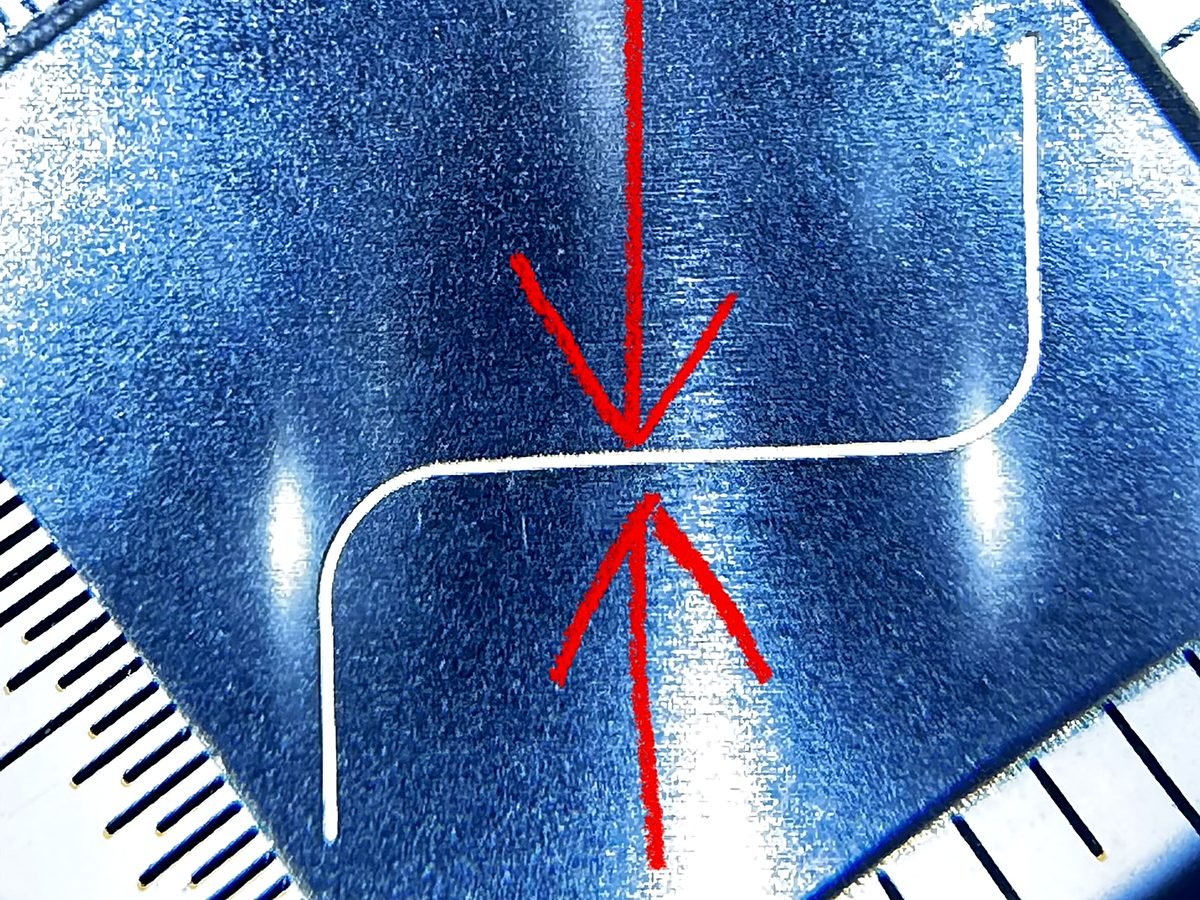
Every cut has width. The laser beam or the abrasive stream removes a thin ribbon of material as it travels, and that ribbon is the kerf. It is small, but on a press fit it is the difference between snug and sloppy. The good news is that you almost never have to account for it yourself, as long as you know where it still shows up.
What kerf is
Kerf is the width of the slot the cutting process removes as it follows a line. Laser kerf is very narrow. Abrasive waterjet kerf is a little wider, because the stream of water and abrasive has real physical width. Either way, material is gone along the cut line, so a part cut to its outline ends up a touch smaller than the raw geometry, and a hole ends up a touch larger, unless something corrects for it.
Both processes handle a wide thickness range, from thin carbon steel around 0.024″ up through 1″ plate, so the same idea applies whether you are cutting a shim or a heavy bracket. What changes with thickness is how much the kerf and its side effects matter, which is the rest of this article.
Kerf compensation is the machine job, not yours
This is the part that saves you the most trouble: you design to nominal geometry, and the machine offsets its toolpath by half the kerf so the finished edge lands exactly on your dimension. The CAM software steers the beam to one side of the line by that half width, so the cut removes material from the scrap side and leaves your part at size.
In plain terms, draw the part you actually want. Do not shrink your outline, do not grow your holes, and do not try to model the kerf into your CAD to compensate. If you do, you are correcting for something the shop already corrects for, and the two offsets fight each other. Design to nominal and let the shop CAM handle the rest.
Where kerf still matters to you
Compensation handles the everyday case, but a few situations still deserve your attention at the design stage:
- Very small holes. Once a hole drops below roughly the material thickness, it gets hard to cut cleanly, because the kerf and the entry and exit of the cut start to dominate the feature. Plan holes at or above the thickness where you can.
- Tight press fits and mating features. Anything that has to slip into or clamp onto another part should be toleranced on the drawing, not assumed. Call out the fit you need rather than trusting a nominal edge.
- Sharp inside corners. A cut cannot leave a truly sharp internal corner. The process leaves a small radius roughly the width of the kerf, because the beam or stream has width and cannot turn on a mathematical point. Design internal corners with a small radius rather than a knife edge.
Waterjet taper on thick plate
There is one more effect worth knowing on thicker material. The waterjet stream loses a little energy as it passes through the plate, so the kerf is slightly wider at the top than at the bottom. That produces a small top to bottom taper on the cut wall. For most parts it is invisible in use and never comes up.
When a perfectly square wall is critical, say a thick part that has to seat flush or mate on its edge, call it out before ordering so it can be controlled rather than left to chance. Naming the critical face is what lets the shop plan for it.
What to expect on tolerance
Kerf is one input into the overall tolerance you can expect, but you do not have to reason about it directly. What matters is the finished numbers. For parts up to 24″ × 24″, standard cutting tolerances are ±0.010″ on outside profiles and large cutouts and ±0.005″ on holes. Design your mating parts with those numbers in mind and the kerf takes care of itself.
If you need tighter than standard, that is available, but it routes to a custom quote so an estimator can confirm it on your specific geometry and thickness. For the full picture, see Cutting Tolerances and what tolerances to expect.
Laser or waterjet, and why it changes the kerf
Because laser kerf is narrower and waterjet kerf is wider, the process choice quietly affects the smallest hole you can cut and how much taper shows on thick plate. You do not have to pick based on kerf alone, but it is one of the reasons the two processes suit different jobs. For a full walkthrough, see waterjet or laser, and the service pages for Laser Cutting and Waterjet Cutting.
A quick worked example
Say you are designing a plate with a 0.500″ hole that has to accept a 0.500″ pin, and a slot that locates a tab. It is tempting to shrink the hole a little to fight the kerf, or to widen the slot to be safe. Do neither. Draw the hole at the size you want the finished feature to be, draw the slot at the width the tab needs, and let the machine offset handle the material the cut removes.
The one place to spend your attention is the fit itself. A pin that has to press in wants a defined tolerance, not a nominal edge, so call out the hole with the fit you need. A tab that has to slide wants a touch of clearance built into the slot. And if that plate is thick, remember the wall may carry a small taper, so an interference fit through the full thickness deserves a second look. In short, design the geometry at nominal and reserve your tolerances for the handful of features that mate.
Practical takeaways
- Do not model kerf into your part, design to nominal geometry
- Tolerance the fits that actually matter, do not assume them
- Avoid holes smaller than the material thickness
- Expect a small radius on every inside corner, about the kerf width
- Flag any wall that must be square on thick plate
- Plan mating parts around ±0.010″ profile and ±0.005″ hole tolerances