What Is K Factor? Bend Allowance in Plain Terms
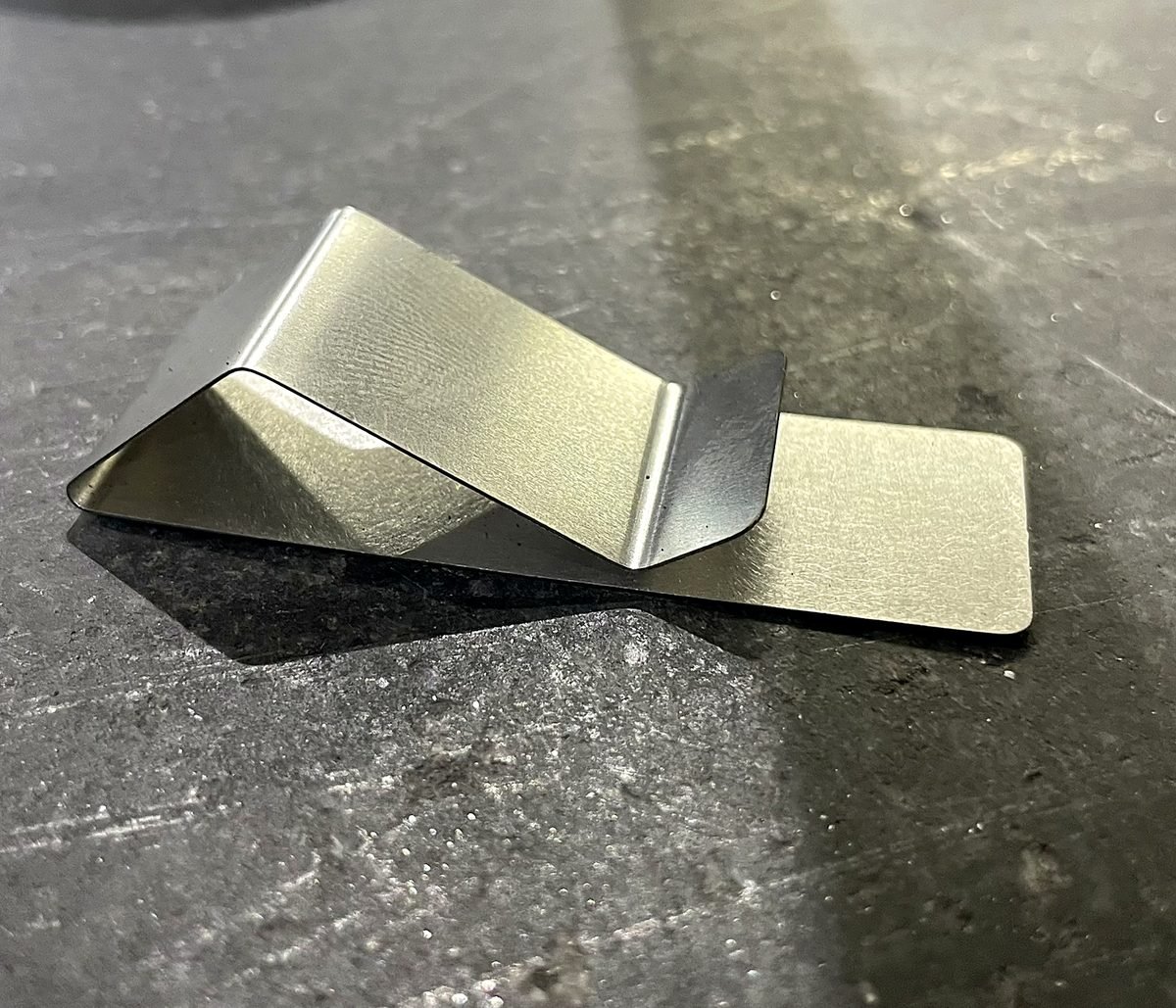
Fold a strip of metal and the outside stretches while the inside compresses. Somewhere between the two sits a line that does neither. Where that line lands is the K factor, and it is what sets the size of the flat blank you have to cut. Get it wrong and a part that measures perfectly in CAD comes off the brake the wrong length.
You do not have to calculate any of this by hand, but understanding it explains why the shop needs the formed shape rather than a flat drawing, and why the radius on a finished part can differ from the one in your model. For the shop side, see Press Brake Bending.
Why a flat pattern is smaller than the sum of the walls
Take a simple L bracket with two legs, each 2″ long. It is tempting to assume the flat blank is 4″ long, the two legs added together. It is not. When you bend sheet metal the outside of the bend stretches and the inside compresses, and the corner itself consumes some length that the two straight legs do not account for.
That consumed length is the bend allowance, and every bent part has one. If you simply add up the flat length of every wall you cut the blank too big, and the finished part ends up longer than the drawing. The flat pattern is always a little shorter than the sum of the outside dimensions, and the K factor is how much shorter.
The neutral axis, the line that does not change
Picture the wall of the bend in cross section. The outer surface is under tension and grows. The inner surface is under compression and shrinks. Between them is one line whose length does not change as the metal forms. That is the neutral axis, and its length is the real length of material you need through the bend.
The neutral axis does not sit exactly in the middle of the sheet. It drifts toward the inside of the bend, because metal compresses more easily than it stretches. Knowing where it sits is the whole game, because that is the length you have to lay flat.
What K factor actually is
K factor is simply the position of the neutral axis, written as a fraction of the material thickness measured from the inside surface of the bend. It runs between 0 and 0.5. A K factor of 0.5 would put the neutral axis dead center; in practice it lands lower, toward the inside, so real values sit below the middle of that range.
- Material shifts it. A soft alloy behaves differently from a hard temper or stainless.
- Thickness shifts it, because thicker stock compresses differently through the bend.
- How tight the radius is shifts it. A sharp bend concentrates the compression and moves the neutral axis further inward than a gentle one.
That is why there is no single correct K factor. It is a small number that captures how a specific material of a specific thickness behaves at a specific radius.
You do not have to solve this by hand
Modern CAD does the arithmetic for you. SolidWorks, Fusion 360, and Onshape all compute the flat pattern from the K factor and the inside radius you set on a sheet metal body. Give them those two inputs and the flat comes out correct, bend allowance and all. The catch is that the software can only do this if you model the part the right way.
What to send ACP for a formed part
Here is the part that saves the most confusion: for a bent part, you do not send the flat. Send a STEP of the finished three dimensional shape, the part as it looks after forming. ACP produces the flat from that geometry and forms to it, so the shop and your CAD agree by construction.
- A formed part needs a STEP of the formed geometry, not a flat DXF.
- A flat part that never gets bent is the opposite case, a clean DXF is right there. The export guide covers both.
- Flag any dimension you consider critical, clearly, so it gets checked rather than assumed.
The radius reality
One more thing K factor teaches you: the inside radius in your model is a target, not a guarantee. The finished inside radius is produced with the closest available tooling for your material and thickness, so it can differ from the nominal value you drew. Because the radius feeds the bend allowance, a different radius shifts the flat slightly too, which is another reason the shop works from the formed geometry.
If a radius is functionally critical, identify it before ordering so it can be reviewed. And remember the tolerances that come with forming: flange dimensions hold to ±0.030″ and bend angles to ±1°. See Forming Tolerances for the detail.
Quick checklist
- Remember the flat is shorter than the sum of the outside walls
- K factor is the neutral axis position, 0 to 0.5 of thickness
- Material, thickness, and radius all move it
- Model a real sheet metal body so CAD can compute the flat
- Send a STEP of the formed part, let ACP produce the flat
- Treat the modeled radius as a target, flag a critical one
- Expect ±0.030″ on flanges and ±1° on angles