Designing Sheet Metal Parts That Bend Right the First Time
Most bent part problems are baked in at the CAD stage, not at the press brake. A shape that looks fine on screen can crack, distort, or refuse to form once it meets real tooling. The good news is that a handful of design rules head off nearly all of it, and every one of them is easy to check before you upload. This guide walks through them in the order you should think about them.
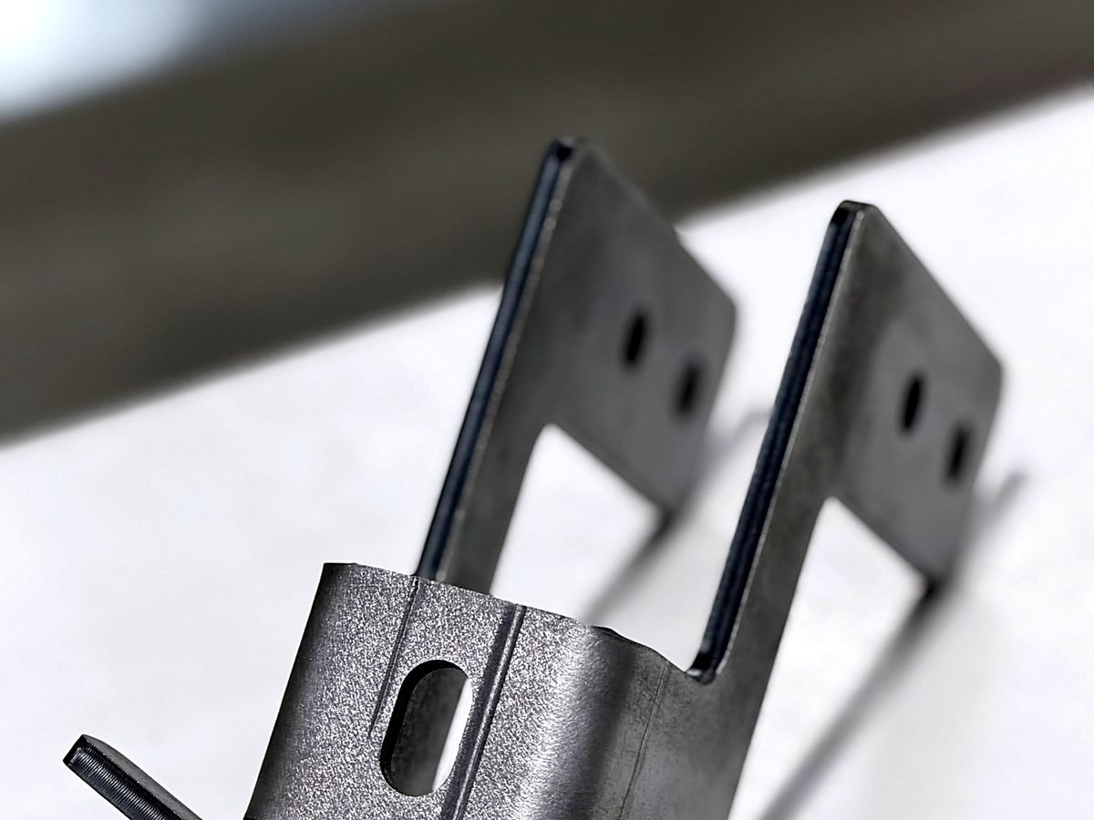
It sits under the broader guide to designing sheet metal parts and focuses only on forming. For the shop side of the same rules, see Sheet Metal Bending and the Press Brake Bending guidelines.
Model the part as a real sheet metal body
Before any single rule, build the part the right way. Model it as a sheet metal body with real bends, not as a flat sketch you extruded or a solid block you hollowed out. When you use the sheet metal features in SolidWorks, Fusion 360, or Onshape, the software keeps thickness, bend radius, and the flat pattern in step with each other, so the numbers below stay consistent as you edit. It also means the flat blank comes out right, which is the whole reason to get the K factor correct.
- One thickness throughout. A formed part is a single sheet, so every wall is the same gauge. Pick that thickness from what the shop stocks so it prices instantly.
- Real bends, not mitered corners. Let the CAD add the inside radius rather than drawing a sharp fold that cannot exist in metal.
- Send a STEP of the formed shape. ACP produces the flat from it, so you do not supply a separate flat for a bent part. The export guide covers the file.
Inside radius: start at the material thickness
When metal bends, the outside stretches and the inside compresses. Ask for too tight a radius and the outside fiber cannot stretch far enough, so it cracks. A safe starting point is an inside radius at least equal to the material thickness. Softer materials tolerate a little less, harder tempers want more.
- 5052 aluminum bends the tightest of the common alloys and is the default for formed enclosures.
- 6061 aluminum is stronger but wants a larger radius, and it can crack at a sharp bend. The full comparison is in 5052 vs 6061 aluminum.
- Stainless is strong but springs back more, so plan for a slightly generous radius.
Give every flange enough length to form
A press brake needs enough material to grip and form each bend. A flange that is too short will not form cleanly and may not stand square. A dependable rule of thumb is to keep every flange, measured from the bend, at least about four times the material thickness plus the inside radius. Shorter flanges are sometimes possible on the right tooling, but treat that as something to review, not to assume. The companion piece, bend radius and minimum flange, works both numbers in more depth.
Keep holes and features clear of the bend
A hole or slot placed too close to a bend distorts into an oval as the metal flows around the corner. Keep holes, slots, and tapped holes back from where the bend starts by at least about two and a half times the material thickness. The same goes for cutouts and any feature you need to stay dimensionally true after forming.
Add a bend relief where a flange ends
When a bend stops partway along an edge, the metal at the end of the bend wants to tear as the flange lifts. A bend relief, a small notch cut at each end of the bend line, gives that corner room to move so it forms clean instead of cracking. Whether a relief is needed depends on the geometry, and the ACP team flags it at quote time rather than letting a part tear on the brake. Adding one yourself in CAD never hurts.
Grain and springback change the result
Two properties of the sheet quietly shape every bend, and neither shows up in a clean CAD model:
- Grain is the direction the metal was rolled. A tight bend along the grain is more likely to crack on the outside, so orient tight bends across the grain where you can.
- Springback is the metal trying to return toward flat after the tool releases. The brake overbends to compensate, but harder materials and stainless spring back more, which is one more reason a generous radius helps.
- Tooling and sequence also matter. The order the bends are formed and the tools available for the job both affect the finished part, which is why a formed geometry, not a wish list of angles, is what the shop needs.
Design inside the ACP forming envelope
ACP forms on TRUMPF TruBend press brakes, including the TruBend 7036 and 1150, using air forming with tooling matched to the job. Keep your part inside these standard ranges and it forms without a special setup:
- Maximum bend length 96″.
- Minimum part size 1″ × 1″.
- Standard thickness range 0.020″ to 0.500″.
Parts outside these ranges are not automatically off the table, but they should be discussed before you commit to the design.
What tolerance to expect on a bend
Forming is repeatable but not infinitely precise. The standard forming tolerances are ±0.030″ on a flange dimension and ±1° on a bend angle. Those apply to a single bend. Across several bends the tolerances stack, so a dimension referenced through three or four bends can drift further than any one of them suggests. Dimension from a single datum where you can, tolerance only the features that are functional, and read Forming Tolerances for the full picture.
Quick checklist
- Modeled as a sheet metal body with real bends, one thickness throughout
- Inside radius at least the material thickness, critical radius flagged
- Flanges at least about four times thickness plus the radius
- Holes and slots kept about 2.5 times thickness from a bend
- Bend reliefs added where a flange ends
- Tight bends oriented across the grain, springback allowed for
- Part inside 96″ bend length, 1″ × 1″ minimum, 0.020″ to 0.500″ thick
- Only functional features toleranced, stacks kept in mind
- STEP of the formed part sent, every operation selected on the order