The Complete Guide to Designing Sheet Metal Parts
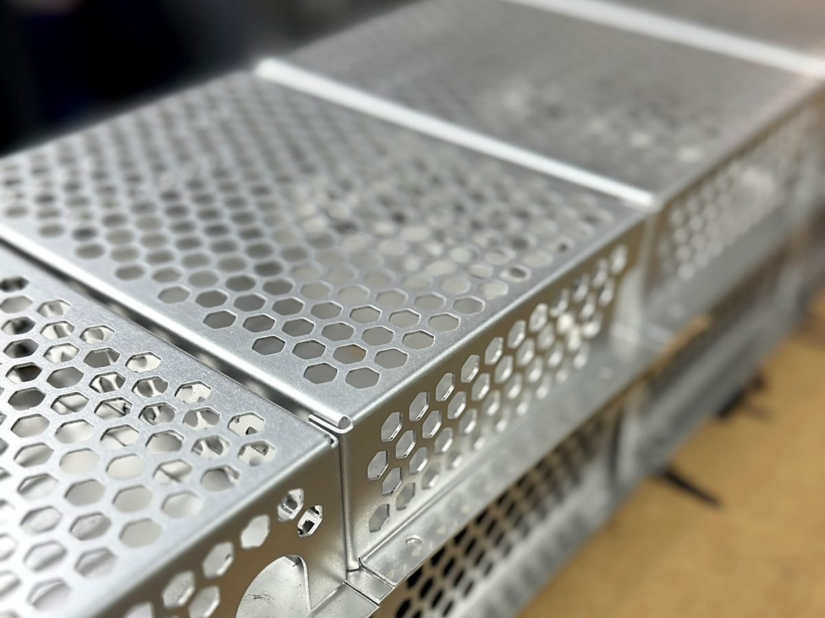
Good sheet metal design is mostly about respecting how the part is actually made. A shape that looks fine in CAD can be slow, expensive, or impossible on the shop floor if it ignores how metal cuts and bends. This guide walks through the design rules that matter, in the order you should think about them, so your parts come out right the first time and price instantly instead of landing in manual review.
It is a map as much as a guide. Each section links to a deeper article and to the matching Manufacturing Guidelines page, so you can go as deep as you need on any one topic.
1. Start with the process
Sheet metal fabrication makes parts by cutting a flat blank and then forming it. Cutting is done on a laser or a waterjet, and forming is done on a press brake. Added operations like tapping, hardware, and finishing happen after. Design your part as a flat pattern with bends, not as a solid block, and most of the rules below fall into place on their own. If your part is really a solid chunk of material, it may belong on a mill instead, see laser cutting vs CNC machining.
2. Choose material and thickness first
Material and thickness drive everything downstream: strength, formability, corrosion resistance, and cost. Pick from what the shop stocks so the part prices instantly. ACP keeps carbon steel, G90 galvanized, 6061 and 5052 aluminum, 304 and 316 stainless, and clear acrylic on the shelf. See the Stocked Materials list.
- Bends a lot: 5052 aluminum or a softer steel.
- Carries load or gets anodized: 6061 aluminum.
- Corrosion matters: 304 or 316 stainless, or plan to coat carbon steel, see preventing rust.
3. Cutting design rules
Cutting removes a thin line of material, the kerf, so a few geometry rules keep small features clean:
- Hole diameter at least equal to material thickness. Smaller holes get difficult as kerf and taper take over.
- Keep holes and slots back from the edge by at least the material thickness, so the thin wall between them does not deform.
- Inside corners cannot be perfectly sharp. The cut leaves a small radius about the width of the kerf. Design mating parts to expect it, see kerf explained.
4. Bending design rules
Forming is where most parts get into trouble, and where a few numbers save nearly every rework. ACP forms on TRUMPF TruBend press brakes with a maximum bend length of 96″, a minimum part size of 1″ by 1″, and a standard thickness range of 0.020″ to 0.500″.
Inside bend radius and the neutral axis
A bend that is too sharp cracks on the outside. A safe starting point is an inside radius at least equal to the material thickness. When metal bends, the outside stretches and the inside compresses; the line between that neither stretches nor compresses is the neutral axis, and where it sits, as a fraction of thickness, is the K factor that sets your flat blank size. Read what is K factor for the full picture.
Minimum flange length
A press brake needs enough material to grip and form a bend, so a flange that is too short will not form cleanly or stand square. Keep each flange, measured from the bend, at least about four times the material thickness plus the radius. Shorter is sometimes possible but should be reviewed.
Keep holes and features away from bends
A hole placed too close to a bend distorts into an oval as the metal forms around it. Keep holes, slots, and tapped holes back from where the bend starts by at least about two and a half times the material thickness. If a hole must sit near a bend, call it out so it can be checked.
5. Holes, threads, and hardware
When a hole needs to hold a fastener, you have two paths, and thickness usually decides which:
- Tapping cuts threads into the sheet itself. It works when the material is thick enough to hold enough threads. ACP taps standard UNC, UNF, and metric sizes, see designing parts for tapping.
- Press in hardware is the answer when the sheet is too thin to tap. A self clinching nut, stud, or standoff locks into the sheet, see designing with press in hardware.
- Countersinks and counterbores seat flat head and socket head fasteners. In a DXF, show only the through hole and call the feature out as an operation, see the Countersinking guidelines.
6. Design for finishing
Decide the finish while you design, not after. Bare carbon steel rusts, so plan on powder coating or plating, or switch to stainless or aluminum. Coating adds thickness, so mating features and tight tolerances should allow for it, and any masking for threads or grounding points should be identified up front. Coating and plating also change lead time, and they must be selected on the order, not just noted.
7. Get the file and order right
Send a STEP for any formed part and a clean DXF only for flat parts, one unique part per file. Then select every operation in the quote, because notes and attachments do not add operations automatically. The export guide covers the file, and the ACP Order Guide covers the rest of ordering.
Design checklist
- Modeled as a flat pattern with bends, not a solid block
- Material and thickness chosen from stock, called out in decimals
- Holes at least one thickness in diameter, kept back from edges
- Inside bend radius at least the material thickness
- Flanges at least four times thickness plus the radius
- Holes and slots kept about 2.5 times thickness from bends
- Bend reliefs added, critical radius flagged
- Threads by tapping, or press in hardware for thin sheet
- Finish decided, with clearance and lead time accounted for
- STEP for formed parts, clean DXF for flat, operations selected